K Type MCB

K Curve MCB Manufacturer in China

Have you ever had this happen—a motor, compressor, or transformer trips the breaker right when it starts? The equipment itself is fine, but you’re left scratching your head, resetting the breaker, and crossing your fingers for the next start.

It’s not a fault in your machinery. It’s a mismatch between how your equipment starts and how your breaker responds.

The K Curve MCB is designed to close that gap—so you get reliable protection without the false trips.

  • ISO
  • CB
  • CE
  • SAA
  • RoHS
Get Catalog
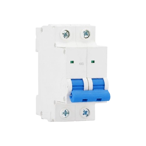
A white two-pole circuit breaker with a central blue switch handle, two green indicator windows, and the marking 'K63' on the front.

Specifications at a Glance

Here are the key specs you'll want to check before making your decision. We've kept it straightforward so you can quickly find what matters for your project.

Why K Curve MCB Is Needed?

Not all breakers are the same. Choosing the wrong one doesn't mean it's defective—it just means it wasn't designed for what you're asking it to do.

Why Standard Breakers Trip on Startup?

Problem

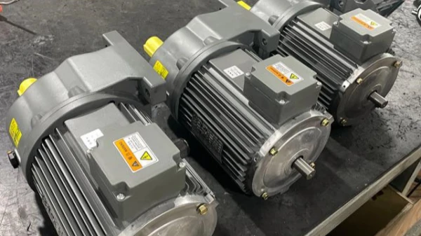
Motors, compressors, and transformers draw a surge of current when they start—often several times higher than their normal running current. A standard breaker sees that surge and treats it like a fault. So it trips. Not because something is broken, but because the breaker wasn't built to tell the difference between a normal startup and an actual problem.

K Curve Is Designed for This Scenario

Solution

Instead of reacting to every current spike, the K Curve MCB is calibrated to allow a higher inrush current before it responds. It gives your equipment room to start normally, while still maintaining the same reliable overload and short-circuit protection you expect from any quality breaker. The result is protection that works with your equipment, not against it.

Fewer Interruptions, Less Wasted Time

Result

The bottom line is simpler: your equipment starts when it's supposed to. You spend less time resetting breakers and troubleshooting false trips, and more time actually running your operation. That means less downtime, fewer service calls, and a more predictable day-to-day. It's not a feature upgrade—it's a reliability upgrade that keeps things moving.

The Takeaway

Insight

A breaker that fits your equipment is a breaker you don't have to think about. It starts when it should, trips only when it needs to, and stays out of your way the rest of the time. That's what K Curve delivers—protection that works so quietly, you almost forget it's there. And when you're not wasting time on nuisance trips and resets, you're spending that time on what actually matters: running your business.

What Is a K Curve MCB?

A K Curve MCB is like any other MCB—except for one thing: the calibration that decides when it trips. And that one difference changes everything.

Some people might wonder: if D Curve already covers the 10–20× In range, why do we need K Curve at 10–14× In? The short answer: they serve different types of loads, and treating them as interchangeable creates a protection gap.

D Curve was built for intermittent, extreme current spikes—welding equipment, UPS systems, X-ray machines. Its philosophy is wide tolerance, trading off some protection precision to avoid nuisance tripping in unpredictable environments.

K Curve was built for predictable, repetitive inrush—motors, compressors, transformers that start and stop routinely. Its narrower window (10–14× In) means it tolerates the startup surge just enough, then trips quickly when a genuine overload occurs during running.

The overlap in the spec sheet can be misleading. Put a D Curve on a motor, and you get tolerance—but the protection gets dull. Put a K Curve on a welder, and it trips when it shouldn’t. They are not alternatives—they are tools for different jobs.

K Curve exists because D Curve is a generalist. And motors need a specialist.

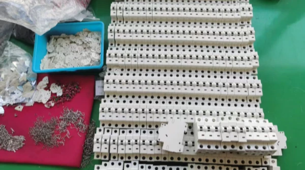
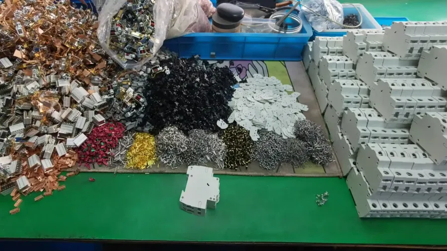
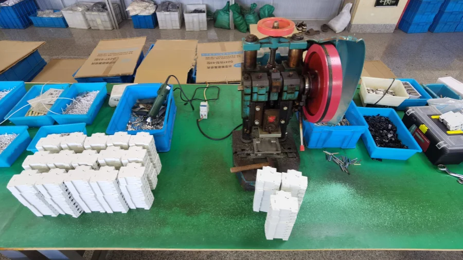
A row of white plastic MCB housings lined up on an assembly table. On the left, there is a blue bin with plastic components, and a red mat with scattered metal internal parts for the circuit breakers.

How the K Curve Actually Works?

Different trip curves exist for a reason. Each one is designed around a specific type of load and startup behavior. The K Curve sits in a particular spot on that spectrum—and once you see where, it's easy to understand why it's the right fit for inductive loads.

K Curve Tripping Chart

The K Curve has two jobs. One: handle the temporary surge when equipment starts—the kind that would trip a standard breaker. Two: react immediately when there’s a real fault, like a short circuit or an overload that doesn’t clear on its own.

On the chart, the shaded band between 10 and 14 times the rated current is where the K Curve operates. Below that, it lets the startup pass. Above or beyond that, it cuts the circuit—fast.

1 1.2 3 10 14 20 Multiples of Rated Current (I / In) 1000s 10s 1s 0.1s 0.01s Tripping Time t (s) Type K Zone (10 ~ 14 In) Thermal Tripping Zone Instantaneous Magnetic Protection Overload / Short-circuit Threshold

How K Curve Compares to B, C, and D?

The table below gives you a side-by-side look at B, C, K, and D curves—so you can see the differences clearly and pick the one that fits your application.

Comparison B Curve C Curve K Curve D Curve
Instantaneous Trip Range 3–5 × In 5–10 × In 10–14 × In 10–20 × In
Inrush Current Tolerance Low Medium High Very High
Suitable Load Type Resistive Loads Mixed Resistive & Inductive Loads Inductive Loads with High Inrush Current Heavy Inductive Loads with Very High Inrush Current
Motor Starting Capability Poor Moderate Excellent Excellent
Risk of Nuisance Tripping High Medium Low Very Low
Recommended Environment Residential Commercial Industrial Heavy Industrial
Protection Characteristics Fast response for sensitive circuits Balanced protection for everyday applications Optimized for high inrush equipment while maintaining reliable protection Maximum tolerance for extreme inrush currents

Reminder

One thing to keep in mind: the exact tripping range for a K Curve MCB can vary depending on the manufacturer and the standard it follows. You might see 8–12 × In, 8–14 × In, or 10–14 × In—all of which are common, depending on who you’re buying from.

On this page, we use 10–14 × In as our reference, since that’s what many international manufacturers adopt for industrial applications. But when you’re looking at a specific model, always double-check the datasheet. And if you’re ever unsure, just confirm with the manufacturer to make sure you’re getting the right specification for your application.

Where K Curve MCB Is Commonly Used?

Five common applications where K Curve MCB is the right fit. Each one has its own startup characteristics—and each one benefits from a breaker that understands them.

Get the Right K Curve MCB for Your Application

Every project has different operating conditions. Share your application requirements with us, and we will help you find a K Curve MCB solution that balances reliable protection with stable equipment performance.

Why Work With Us?

You're not just looking for a box of MCBs. You're looking for someone who solves your problem, delivers on time, backs up their products, and actually picks up the phone when something comes up. Here's what that looks like in practice.

Case Study

See how a water treatment facility improved motor startup reliability by selecting a protection solution matched to high inrush current applications.

Eliminating Motor Startup Tripping Problems in a Water Treatment Plant

  • Industry
    Municipal Water Treatment
  • Location:
    Australia
  • Equipment
    7.5kW-15kW Three-Phase Motors
  • Original Issue
    3-5 Trips Per Month

Background

A municipal water treatment facility in Queensland, Australia, is responsible for providing daily water treatment services for the local community.

To keep the operation running around the clock, the facility uses multiple automated pumping systems controlled by PLCs. The pumps start and stop automatically based on water levels and operational demands—no manual intervention, just continuous, unattended operation.

The system includes four centrifugal pumps with 7.5kW to 15kW three-phase induction motors, all protected by DIN rail mounted circuit breakers. The facility runs 24 hours a day, seven days a week, so any unexpected shutdown doesn’t just affect efficiency—it creates extra work for the maintenance team.

During routine operation, the team noticed a recurring issue: certain pump motors would trip their MCBs during startup.

Once the motors were running, they performed normally. But the interruptions kept happening, and each one required someone to go out, reset the breaker, and get the system back online.

The Challenge

At first, the engineering team suspected that the problem was caused by motor overload. To get to the bottom of it, they ran a full inspections of the entire electrical system.

They started with the motors themselves. Testing confirmed that the motors were operating within normal parameters, with no abnormal current draw, no winding issues, no mechanical faults detected.

Next, they reviewed the electrical installation, including cable sizing, voltage drop, and rated capacity. Everything checked out. No design errors, no capacity issues.

After those basic checks came back clean, they moved on to startup current analysis. The data showed a significant surge during motor energization-the startup current spiked several times higher than the normal operating current.

  • Normal Operating Current18A
  • Startup Current Peak120-150A
  • Current Surge Level7-8× In

So the problem wasn’t the motors. It wasn’t the wiring. It was a mismatch between the breaker’s trip characteristic and the motor’s inrush behavior.

Normal running current:18A. Startup peak: 120-150A. That’s roughly 7 to 8 times the normal draw. The existing C Curve MCBs weren’t built to handle that kind of gap-so they tripped, even though nothing was actually wrong.

The Solution

Instead of simply upsizing the breakers, the engineering team focused on finding a protection solution that actually matched the motor’s startup characteristics.

After analyzing the startup current behavior, they replaced the existing C Curve MCBs with K Curve MCBs. The K Curve is calibrated to allow a higher inrush current before it responds—exactly what the motors needed during startup.

The upgrade was done during a scheduled maintenance shutdown. The existing control cabinet, wiring system, and overall electrical design stayed the same—just the breakers were swapped out. No major modifications, no extra downtime beyond the scheduled window.

By upgrading only the protection devices, the facility achieved a better protection configuration while keeping the original system layout intact. Everything else stayed exactly as it was.

Results

  • 0

    Startup Related Trips

  • 6 Months

    Stable Operation Period

  • 100%

    System Compatibility

After the upgrade, the facility saw immediate improvement. The motors started cleanly every time. No trips during startup.

Six months later, the system is still running without a single startup-related trip. The maintenance team no longer spends time resetting breakers or chasing false alarms.

The solution was fully compatible with the existing system—no rework, no added cost, no surprises. Just stable, reliable operation.

We thought the problem was with the motors or wiring. Turned out it was the breaker curve all along. After switching to K Curve, the startup process became stable, and our team doesn't have to deal with frequent trips anymore.

— Michael R.
Electrical Maintenance Supervisor

FAQs

Still have questions? Here are answers to some of the most common questions about K Curve MCBs.

Ready to Find the K Curve MCB?

Send us your requirements—we'll get back to you within 24 hours with a recommendation that fits your application.