DC Miniature Circuit Breaker

DC MCB Manufacturer in China

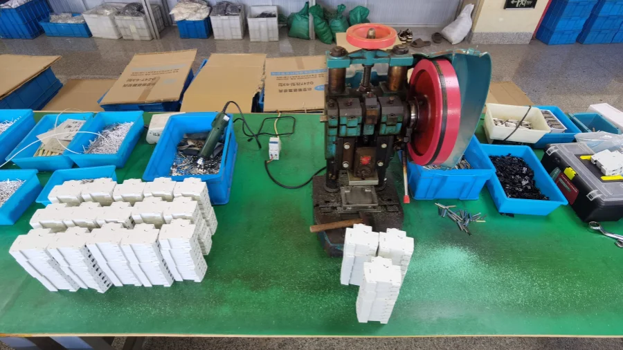
DC circuits need breakers that are made for DC. Unlike AC, the current doesn’t drop to zero — so the arc lasts longer and puts more stress on the contacts.

We build our DC MCBs to handle exactly that. Stronger arc chambers, better contact materials, and ratings that match real DC applications.

Tell us about your project, and we’ll help you find the right protection.

  • ISO
  • CB
  • CE
  • SAA
  • RoHS
Get Catalog
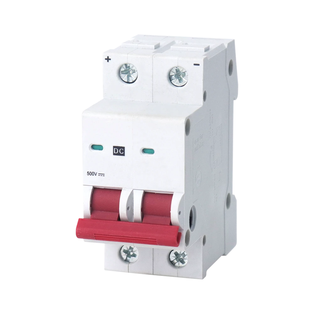
A white-background product close-up showing a gray and white two-pole DC MCB. The top terminals are marked with '+' and '-' polarity symbols, and the front face features the 'DC' logo and '500V' DC rated voltage parameter. A red linked operating handle is located at the bottom, representing a key safety protection and switching control component in DC power distribution systems.

DC MCB Key Specifications

Here's a quick look at what our DC MCBs cover.

Not Sure Which DC MCB to Choose?

Share your project requirements with us, and we'll recommend the right solution.

Why DC MCB?

Why DC Circuits Need a Different Breaker?

Most MCBs you come across are designed for AC — that’s just how the market has traditionally worked.

But when you put an AC breaker in a DC circuit, the conditions change, especially when a fault happens and the breaker needs to interrupt the current.

How AC and DC Behave Differently?

AC and DC behave differently when a circuit breaker interrupts a fault.

AC

AC current periodically passes through zero as its waveform changes direction.

When the breaker contacts open and an arc forms, this periodic zero crossing gives a natural chance for the arc to extinguish.

Zero-Crossing +I_peak 0 A -I_peak Current / Voltage (I / V) Time (t) 1 Cycle Period T (50Hz = 20ms) + Positive Half Cycle - Negative Half Cycle

DC

DC current flows continuously in one direction and never drops to zero.

So when the breaker opens, the arc doesn’t have that same natural break — it lasts longer and puts more stress on the contacts.

Constant Direct Current / Voltage (I_dc / V_dc) No Zero-Crossing +I_dc 0 A Current / Voltage (I / V) Time (t) Single Polarity (Continuous Flow)

Why Can't an AC MCB Simply Be Used in a DC Circuit?

At first glance, it might seem fine to use an AC MCB in a DC circuit if the voltage and current ratings match. But a breaker’s ability to protect a circuit isn’t just about its normal operating ratings — it’s about what happens during a fault.

When a fault occurs, the breaker needs to open the circuit, control the arc, and complete the interruption safely. In AC, the zero-crossing helps with that. In DC, there’s no zero-crossing to assist. So an MCB that hasn’t been rated and verified for DC conditions isn’t safe to use in a DC circuit, even if the numbers on the label look right.

What Can Happen During Interruption?

  • Persistent Arcing

    The arc may be more difficult to extinguish because the DC has no zero crossing point.

  • Contact Erosion

    A longer arc creates more heat and electrical stress, wearing down the contacts.

  • Contact Welding

    In severe cases, the heat can damage the contacts or cause them to weld together.

  • Unreliable Interruption

    If the arc isn't controlled, the breaker may not interrupt the fault reliably

What Is a DC MCB?

DC MCBs are built specifically for DC interruption. The design has to handle the arc without relying on a zero-crossing.

That means the contact system, arc-extinguishing structure, voltage rating, breaking capacity, and polarity configuration all need to be designed for DC conditions.

These elements work together so the breaker can do its job reliably when a fault occurs, not just during normal operation.

DC MCB for Different Applications

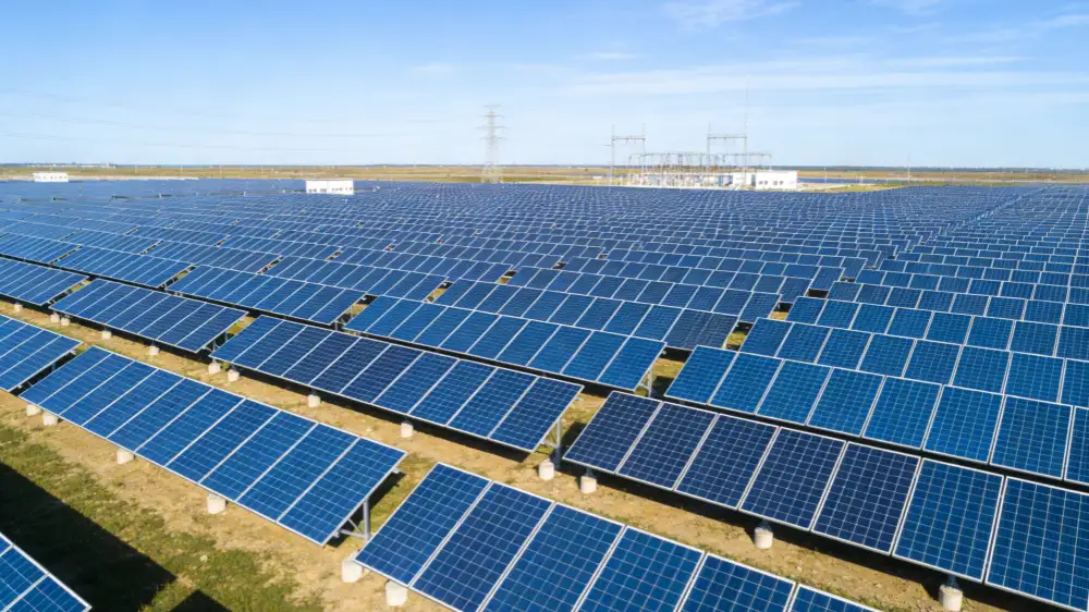
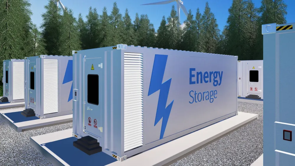
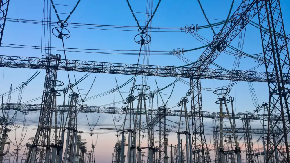
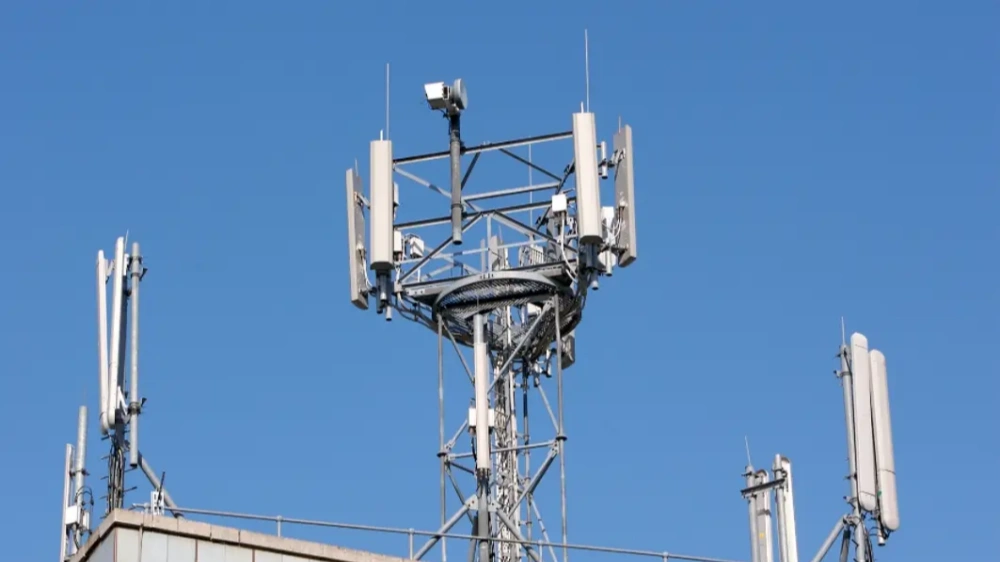
DC MCBs are used in a range of systems where DC circuits need protection. The applications below are some of the most common — each with its own requirements for voltage, current, and fault protection.

Why Licen for DC MCB Solution?

You‘re not just looking for a box of MCBs. You’re looking for an expert who solves your problem, delivers on time, backs up their products, and actually picks up the phone when something comes up. Here‘s what we offer — and what it means for your day-to-day.

Case Study

Here's a real-world engineering scenario showing how reviewing PV string conditions helped refine DC MCB selection on a commercial rooftop solar installation.

Rechecking DC MCB Protection After PV String Configuration Changes

  • Industry
    Commercial Solar
  • Application:
    Rooftop Photovoltaic System
  • Equipment
    PV Modules, String Combiner Boxes & Inverters
  • System Capacity
    Approximately 420 kW
  • Original Configuration
    DC MCBs Selected During Initial PV Design

Background

A commercial warehouse in Queensland was installing a new rooftop PV system to reduce daytime electricity consumption from the grid. The project totaled about 420 kW of PV capacity, distributed across several roof sections.

The system used multiple PV strings connected to string inverters. Each string was a series-connected group of modules, grouped within DC combiner arrangements before connecting to the inverter inputs.

The original design was based on the expected module characteristics and the inverter manufacturer’s input requirements. DC protection devices were initially selected around the anticipated string current and system voltage. At the design stage, the arrangement looked straightforward.

During construction, however, the contractor made several practical adjustments to the string layout. They had to work around roof obstructions, equipment access paths, and the actual location of the inverter cabinets.

Some strings became longer than originally planned. The number of parallel strings connected to several inputs was also adjusted.

None of these changes significantly affected the overall PV capacity. But they did change the electrical conditions that the DC protection devices were expected to operate under.

Before final commissioning, the electrical contractor decided to review the DC protection configuration against the installed system — rather than relying solely on the original design calculations.

The Challenge

The first step was to verify the actual electrical characteristics of the installed PV strings.

The PV modules had a nominal maximum power current of approximately 13 A, with an open-circuit voltage of around 50 V per module under standard test conditions. With 10 modules in series, a typical string operated at roughly 400–450 V DC, and the open-circuit voltage increased further under low temperatures.

  • PV String Configuration10 Modules in Series
  • Maximum Power CurrentAround 13 A
  • Open-Circuit VoltageAround 500 V DC
  • Typical Operating Voltage400 – 450 V DC
  • String Cable Size4 mm²
  • Longest String RunAround 65 m

The operating current itself wasn’t particularly high. The more important question was whether the protection devices were correctly matched to the actual DC voltage and fault conditions.

The engineering team identified three areas that required closer review.

1. DC Voltage Was Higher Than the Nominal System Description Suggested

The system was generally referred to as a “400 V DC PV system” throughout the project. However, the actual open-circuit voltage of a string could approach 500 V DC under certain conditions. This meant the MCB’s DC voltage rating couldn’t be selected simply from the nominal operating voltage — the maximum possible PV string voltage had to be considered.

2. Parallel Strings Could Increase Available Fault Current

A single PV string has limited short-circuit current. But when multiple strings are connected in parallel, current from healthy strings can contribute to a fault on another string. A group of four parallel strings, for example, could potentially deliver substantially more fault current to a faulted branch than a single string could provide by itself. The team therefore reviewed the number of parallel strings connected to each protection point, rather than evaluating each string in isolation.

3. The DC Breaking Requirement Needed to Be Verified

The original protection selection had focused heavily on the string current rating. The commissioning review highlighted that the MCB also needed an appropriate DC interruption capability.

This was particularly important because DC current doesn’t naturally pass through zero the way AC current does. Once a DC arc is established, interrupting it requires the protection device to be specifically designed for the DC circuit conditions. The team reviewed the MCBs against the actual PV voltage, expected current, available fault current, and the manufacturer’s specified DC breaking capability.

The Solution

Rather than changing the PV modules or inverter configuration, the contractor revised the DC protection selection for the affected string circuits.

The replacement devices were selected specifically for photovoltaic DC applications and verified against the maximum expected system voltage. Their DC breaking capacity and pole configuration were also checked against the installation requirements.

The string current remained within the original design range, so there was no need to increase the protection rating simply because the strings were longer. This was an important part of the review — increasing the MCB rating wouldn’t have solved the underlying protection-selection issue.

Instead, the contractor kept the protection rating appropriate for the PV string and conductor while ensuring the device itself was suitable for the DC voltage and fault-interruption requirements.

The revised selection process looked at the complete chain:

PV module characteristics → string voltage → string current → number of parallel strings → cable length → available fault current → MCB voltage rating → DC breaking capacity

The contractor also checked the polarity and connection arrangement of the DC MCBs before installation. This was particularly important because the manufacturer specified different connection requirements depending on the pole configuration and DC application.

After installing the new protection devices, the contractor carried out the normal commissioning checks for the PV DC circuits — polarity verification, insulation resistance testing, string voltage measurements, continuity checks, and verification of the protective-device configuration.

The measured string voltages were consistent with the expected design values, and the DC protection devices were confirmed to be suitable for the installed operating conditions.

Results

  • PV System CapacityAround 420 kW
  • Typical String CurrentAround 13 A
  • Maximum String VoltageAround 500 V DC
  • Typical Operating Voltage400 – 450 V DC
  • Longest String RunAround 65 m
  • ApplicationRooftop PV String Protection
  • Protection TypePV-Rated DC MCB
  • System ModificationDC Protection Selection Review

The revised protection arrangement didn’t require any major changes to the PV system. The modules, string configuration, cable sizes, combiner arrangements, and inverters remained essentially unchanged. The main improvement came from matching the DC MCB specification more closely to the actual electrical conditions of the installed system.

The project also highlighted an important lesson for PV system design. A DC MCB cannot be selected simply by looking at the PV string’s operating current. For photovoltaic applications, the protection device needs to be considered against several conditions at the same time:

Maximum PV voltage

The MCB’s DC voltage rating needs to accommodate the maximum possible string voltage, including the effect of low temperatures on PV open-circuit voltage.

String and parallel current

The protection arrangement needs to consider not only the current from an individual string, but also the potential contribution from parallel strings under fault conditions.

DC breaking capacity

The device needs to be capable of interrupting the expected DC fault current at the applicable system voltage.

Installation configuration

Pole arrangement, polarity, wiring method, and manufacturer-specific connection requirements all need to be checked as part of the installation.

The final commissioning review shifted the team’s approach from:

“The string current is 13 A, so a suitable MCB should simply be around that rating.”

to:

“The MCB needs to be suitable for the complete PV circuit — including maximum DC voltage, fault current, breaking capacity, and installation configuration.”

Engineering Takeaway

PV systems operate under conditions that are different from conventional AC distribution. DC voltage can remain present whenever the PV modules are illuminated, and multiple parallel strings can contribute to fault conditions.

For this reason, selecting a DC MCB for photovoltaic applications should involve more than matching the breaker rating to the normal string current. A proper review should consider:

Voc × temperature correction → operating current → parallel strings → cable characteristics → prospective fault current → DC voltage rating → DC breaking capacity

The right protection device isn’t simply the one with the correct ampere rating. It’s the one whose electrical characteristics match the actual PV circuit it’s protecting.

The final protection selection was not driven by the nominal string current alone. We had to look at the maximum DC voltage, parallel-string fault contribution, and the breaker's actual DC interruption capability before confirming the final configuration.

— David Chen
Electrical Project Engineer

FAQs

Quick answers to the most common questions we get about DC MCBs.

Let’s Find the Right DC Protection Solution

Every DC system has different protection requirements. Share your project details with us to find the right DC MCB for your system.