B Type MCB

B Curve MCB For Circuits That Don't Need a High Trip Threshold

Imagine you’re running a circuit across a building — cable from the distribution board down a long corridor, feeding a few points along the way. Nothing unusual.

Now picture a fault at the far end. The breaker should trip and clear it. But because the cable is long, the resistance limits the fault current. The current never reaches the trip level of a standard breaker, so the fault just sits there.

That’s what B Curve is made for. It responds at a lower fault current, so it catches faults that might otherwise go unnoticed. It’s not about being overly sensitive — it’s about matching how circuits actually behave in the field.

  • ISO
  • CB
  • CE
  • SAA
  • RoHS
Get Catalog
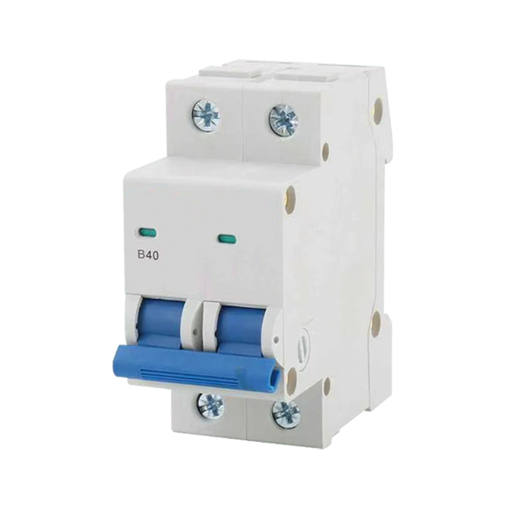
A white B40 2-pole miniature circuit breaker with a blue toggle handle and top/bottom terminal screws, used for electrical overload and short-circuit protection

B Curve MCB Specifications

Here's a quick rundown of the standard specifications for our B Curve MCBs – the key details you'd want to check when selecting a breaker for your distribution board.

Why B Curve?

When a Fault Current Isn't High Enough.

Most people think a short circuit means a huge surge of current. But in the real world, that's not always the case. The actual fault current depends on the circuit itself. Sometimes that fault current ends up being a lot smaller than you'd expect.

The Problem

When Fault Current Is Low, the Circuit Changes.

When a fault occurs, the current that actually flows isn’t determined by the supply alone. The whole fault loop comes into play – the cables, the connections, the distance, and the characteristics of the supply itself.

Longer cable runs add resistance. Smaller conductors add resistance. Supply conditions vary from site to site. All of these factors can hold back the current that flows during a fault.

The end result is a situation that’s easy to miss: the fault is there, but the current isn’t nearly as high as you might expect. And if your breaker is set to respond only at higher levels, it may not do its job when it needs to.

Protection Need

Protection Has to Fit the Actual Conditions.

A protection device needs to be selected for the actual conditions it will face, not for an idealised version of them. Every circuit is different, and the fault-current characteristics vary widely from one installation to the next.

Some circuits are capable of delivering high fault currents. Others simply aren’t. Using the same protection approach for both is a gamble – and it’s one that can leave you exposed where you least expect it.

When the available fault current is limited, the trip characteristic of the breaker becomes a critical factor in the protection design. It’s not enough to match the current rating and move on. You need to be confident that the breaker will actually respond under the conditions that exist on that circuit.

The Implication

Different Circuits Ask for Different Things.

Circuit protection isn’t simply a matter of choosing a device with the correct current rating. The electrical conditions of the circuit also influence which protection characteristic is appropriate.

For circuits where the available fault current may be relatively low, the ability of the protection device to respond under those conditions becomes an important consideration in the overall design. You can’t just look at the nominal current and call it done.

The real question is: will this breaker do its job under the actual conditions it will face? Not the ideal ones, not the textbook ones – the real ones. That’s what makes the difference between protection that works and protection that just looks good on paper.

The B Curve Approach

This Is Where B Curve Makes Sense.

B Curve breakers are designed for circuits where the available fault current may be on the lower side. They offer a protection characteristic that aligns well with these conditions, which is why they’re a common and practical choice in many installations.

The value of a B Curve comes down to a simple requirement: providing effective protection for circuits where fault currents aren’t extreme. In those applications, it offers a straightforward, dependable solution.

B Curve breakers respond at a lower threshold, so they’re able to clear faults that other breakers might not catch. Not because they’re designed to be more sensitive, but because their trip characteristic matches the reality of these circuits. It’s about getting the match right – and that’s what makes the difference.

A fault doesn't always mean a massive current. B Curve starts from that simple fact, and everything else follows from there.

What Is a B Curve MCB?

A B Curve MCB is a miniature circuit breaker with a specific time-current tripping characteristic.

The term “B Curve” refers to how the breaker’s tripping characteristic is defined – it’s not about a different physical construction or a special type of device. It’s simply a standardised way of describing when the breaker will trip under fault conditions.

Under IEC 60898-1, a B Curve MCB has an instantaneous tripping range of around 3–5 times its rated current (In). This is considered a relatively low instantaneous tripping range, which makes it particularly relevant for circuits where the available fault current may be on the lower side.

In practice, this means the B Curve is well-suited for circuits that don’t generate extreme fault currents but still need reliable protection. It’s a straightforward, standardised solution for a common set of electrical conditions.

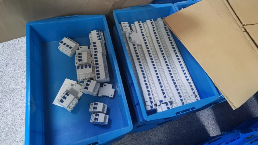
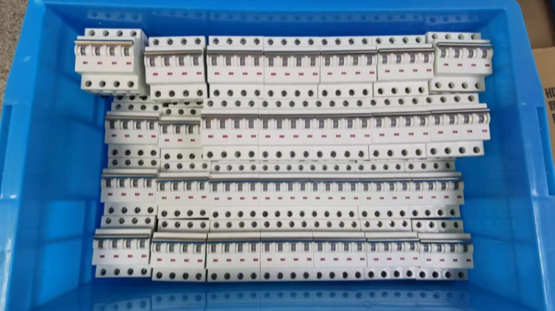
A blue plastic storage bin neatly packed with a full box of miniature circuit breakers, showing a sufficient stock of electrical components.

How Does a B Curve MCB Actually Work?

Let's take a look inside the B Curve breaker – what's actually going on when current flows through it, and why it responds differently from other curves.

Understanding the B Curve Chart

Take a look at the chart beside this text. The blue area shows the B Curve’s instantaneous tripping zone – it spans from 3 to 5 times the rated current. Within this range, the breaker trips almost instantly when a fault occurs.

Below that range, the response comes from the thermal mechanism instead – slower, but still providing protection.

The boundary between thermal tripping and magnetic tripping is what defines the B Curve. And that boundary is set lower than C or D Curve – which is exactly why this breaker behaves differently from others.

1 1.13 3 5 10 20 50 Multiples of Rated Current (I / In) 1000s 10s 1s 0.1s 0.01s Tripping Time t (s) Type B Zone (3 ~ 5 In) Thermal Tripping Zone Instantaneous Magnetic Protection Inrush Withstand / Short-circuit Limit

How B Curve Compares to C, D?

The difference between B, C, and D Curve breakers comes down to one thing: where they set the instantaneous trip threshold. The table below shows how they compare, and why B Curve is the right fit for certain circuits.

Comparison B Curve C Curve D Curve
Instantaneous Trip Range 3–5 × In 5–10 × In 10–20 × In
Instantaneous Trip Threshold Lowest
Lower instantaneous tripping range
Moderate
Higher than B Curve
Highest
Higher than B and C Curve
Response to Lower Fault Currents Higher responsiveness
Enters the instantaneous trip range at a lower current level
Moderate
Requires a higher current level
Lower
Requires a significantly higher current level
Inrush Current Tolerance Lower
More sensitive to high startup currents
Moderate
Greater tolerance than B Curve
Higher
Suitable for higher inrush conditions
Key Characteristic Lower instantaneous tripping threshold
Particularly relevant when available fault current may be limited
Balanced threshold
Suitable for circuits with moderate transient currents
Higher instantaneous threshold
Suitable for circuits with higher transient currents
Typical Circuit Conditions Circuits with relatively low inrush current and potentially limited fault current. Circuits with moderate starting or transient current requirements. Circuits with high starting or transient current requirements.
Typical Load Characteristics Low-inrush or predominantly resistive loads
Where high startup current is not expected
Moderate-inrush loads
Where some startup current may occur
High-inrush loads
Where substantial startup current may occur
Fault Current Conditions More relevant where fault current may be relatively low More suitable where higher fault current is available Generally requires higher fault current to reach instantaneous tripping
Starting Current Consideration Startup current should remain sufficiently below the instantaneous trip range Provides more allowance for startup current than B Curve Provides the greatest allowance for high startup current
When B Curve Becomes Relevant When a lower instantaneous trip threshold is beneficial for the circuits fault-current conditions. When a higher threshold is preferred to accommodate moderate transient currents. When a substantially higher threshold is required to accommodate high transient currents.
Selection Focus Lower instantaneous tripping range
Prioritizes response under relatively limited fault-current conditions
Balanced protection and transient-current tolerance Higher transient-current tolerance

Where B Curve MCBs Are Commonly Used?

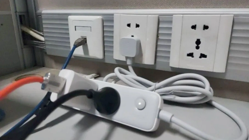
B Curve breakers show up in a lot of different installations. Not because they're a special or unusual choice – they're actually quite standard. But they tend to be a good fit for certain types of circuits more than others. Here are some of the most common places you'll find them.

Why Licen for This Solution?

You're not just looking for a C Curve MCB. You're looking for a supplier that understands the application, gets the specification right, delivers consistently, and supports you when something needs attention.

Case Study

Here's a real example of how matching the MCB curve to actual circuit conditions made a difference on a commercial office project.

Switching from C Curve to B Curve for Lighting and Socket Circuits

  • Industry
    Commercial Building
  • Application:
    Lighting & Socket Circuits
  • Equipment
    Single-Phase Distribution
  • Original Configuration
    C Curve MCBs

Background

A three-storey commercial office building in Queensland was going through an electrical refurbishment. The job included upgrades to several distribution boards and final circuits.

The building had a mix of LED lighting, general-purpose socket outlets, office equipment, and small auxiliary loads. Most of the circuits carried relatively stable loads with limited inrush current.

A few final circuits were on the longer side because the distribution boards were centrally located – they were away from some tenant areas and common spaces. The contractor went with C Curve MCBs across the board as their standard choice.

During commissioning, they ran the usual tests – insulation resistance, continuity, polarity, and protective-device verification.

The connected loads were all working fine, but the test results showed something interesting: some of the longer downstream circuits had lower prospective fault current than expected.

The Challenge

The engineering team decided to take a closer look at those circuits before finalizing the protection configuration.

Instead of just increasing the breaker rating, they went through the full circuit characteristics, including conductor size, circuit length, measured impedance, normal operating current, and prospective short-circuit current.

What they found was that these circuits were mainly feeding lighting and general-purpose socket loads. These loads don’t demand much on startup, but the longer cable runs added impedance, which meant lower available fault current at the far end.

Typical measurements on the circuits under review were:

  • Normal Operating Current8 – 12 A
  • Circuit Length35 – 55 m
  • Prospective Fault CurrentAround 70 – 100 A

The C Curve MCBs were fine in terms of rated current. But the team started to question whether the magnetic tripping characteristic was actually the right match for these circuits.

The goal wasn’t to find a “more sensitive” breaker. It was to make sure the protection would actually work under the real conditions – and still stay stable during normal operation. That meant looking at the trip curve together with the actual circuit impedance and fault current, not just in isolation.

The Solution

After reviewing the test results and circuit characteristics, the contractor decided to switch to B Curve MCBs for the affected lighting and socket circuits.

B Curve MCBs have a lower instantaneous magnetic trip range, typically around 3–5 times rated current, compared with higher-trip that are often used on circuits with more demanding startup conditions.

For the low-inrush loads in this building, the B Curve characteristic lined up much better with what the measurements were showing.

The good thing was, this change didn’t require a redesign of the distribution system. The existing cables, distribution boards, and connected equipment all stayed the same. The only thing that changed was the MCB curve on the circuits where the review supported it.

After installation, the circuits were tested again as part of the commissioning process. The contractor verified the protective-device characteristics against the measured circuit conditions before handling over the installation.

Results

  • Protection CurveB Curve
  • Typical Circuit Current8 – 12 A
  • ApplicationLighting and Socket Circuits
  • System ModificationMCB Selection Only

The revised setup gave the affected low-inrush circuits a protection characteristic that was a much better fit.

More importantly, the project gave the contractor a clearer way of thinking about MCB selection. Instead of applying the same curve across the board, they started selecting protection devices based on the actual load characteristics, circuit impedance, and available fault current of each circuit.

The project also highlighted an important point: rated current alone does not tell you whether a particular tripping curve is right for the job.

For lighting and general-purpose socket circuits with relatively low inrush current, B Curve MCBs are worth considering – provided the measured circuit conditions and protection requirements actually support the choice.

The circuit ratings were correct from the beginning. What we needed to revisit was the tripping characteristic. Once we looked at the actual circuit length and fault-current conditions, the B Curve was a better fit for those circuits.

— Daniel Mercer
Electrical Project Engineer

FAQs

Got questions about B Curve MCBs? Here are answers to some of the most common ones we hear.

Ready to Start Your Project?

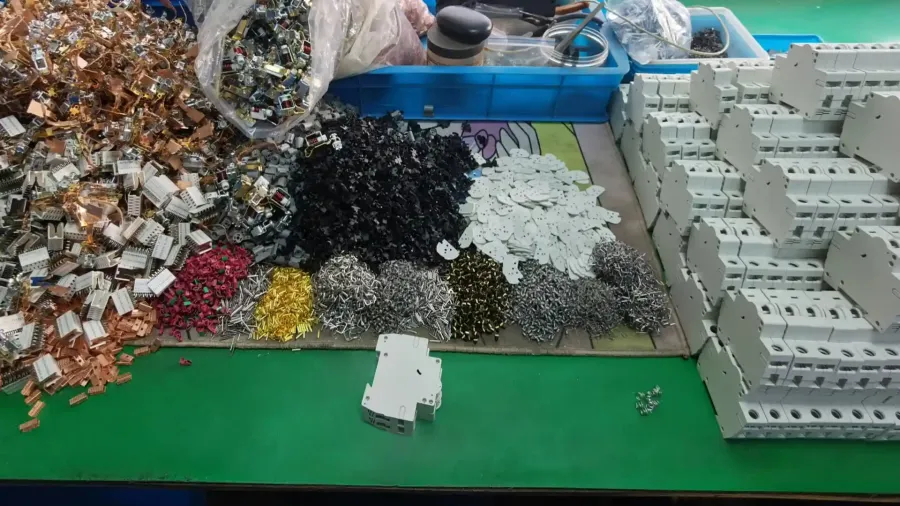
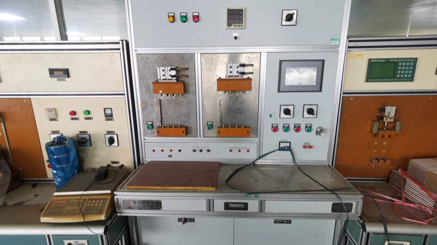
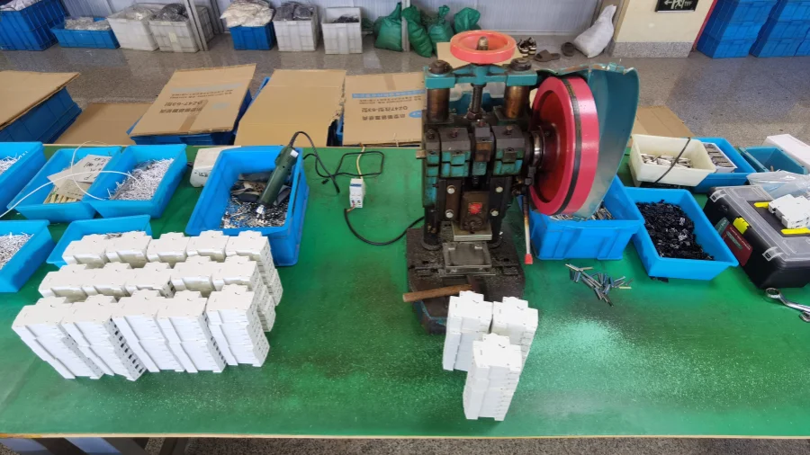
We manufacture B Curve MCBs in-house and supply them to projects around the world. If you'd like a quote or just have questions, reach out.