
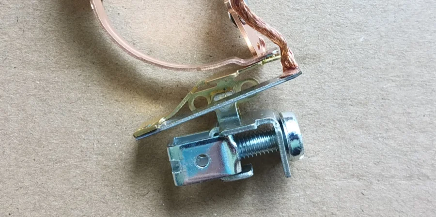
Customers who buy breaker components from us often ask the same question: “How do we adjust the thermal sensitivity of the breaker?”
It’s a fair question. The thermal element plays an important role in determining when the breaker trips, so getting the sensitivity right is an important part of MCB production.
So, how is thermal sensitivity actually adjusted? Let’s take a closer look.
The Core Mechanism
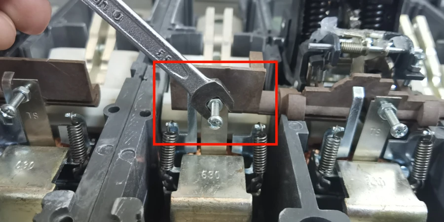
The most common adjustment method across virtually all mechanical circuit breakers — from small MCBs to larger MCCBs — is a calibration screw that changes the gap between the bimetal strip and the trip bar (or trip latch).
This is the central mechanism, and everything else in the calibration workflow is built around it.
The Gap Is the Variable That Matters
When the bimetal bends under heat, it needs to travel a certain distance before it physically contacts or pushes the trip bar. That travel distance is the trip gap. The calibration screw can adjust this gap.
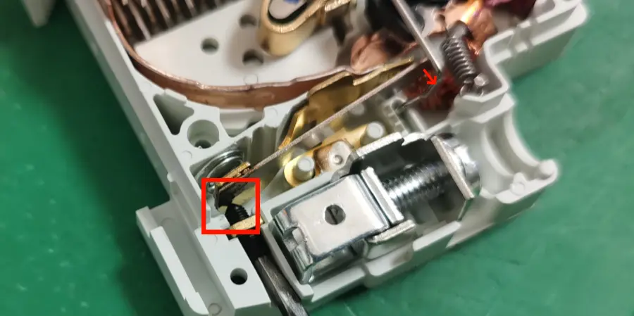
The spacing between the end of the bimetal and the contact leg of the trip bar may be adjusted to change the response time of the circuit breaker to overload conditions by appropriately turning the screw — rotation of the screw moves a lever to pivot the bimetal, shifting its effective trip position.
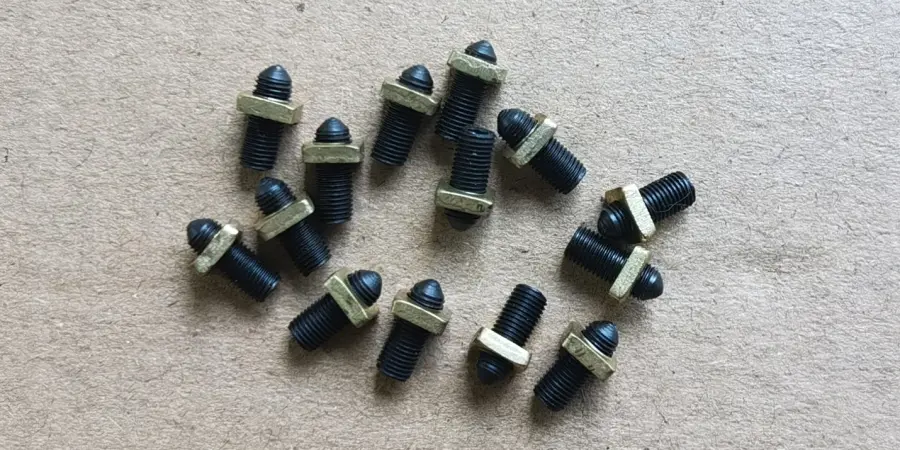
In practical terms:
- Tightening the screw (reducing the gap) → the bimetal needs less deflection to reach the trip bar → the breaker trips faster → thermal sensitivity is higher
- Loosening the screw (increasing the gap) → the bimetal needs more deflection → the breaker trips slower → thermal sensitivity is lower
This principle applies to almost every mechanical breaker design, regardless of the brand or factory. The exact design may vary.
In some breakers, the screw directly contacts the bimetal foot, while in others, it works through an intermediate lever arm. But the basic principle remains the same.
Why the Screw Position Matters So Much in Production?
The calibration screw is located near the hot end of the bimetal strip, and its position has a direct effect on the circuit breaker’s tripping time. This makes the thermal trip mechanism one of the key parts of the breaker.
In production, even a small difference in screw position can affect the final time-current test results. And even if every screw is tightened to exactly the same torque, some variation is still normal. The reason is that other parts also have their own tolerances.
The bimetal strip may vary slightly in size, the heater resistance may not be exactly the same, and the trip bar geometry can also vary from one unit to another.
That’s why calibration is not simply a matter of setting the screw once. Each breaker needs to be tested and adjusted to make sure it falls within the required range.
| Adjustment Direction | Gap Change | Deflection Needed | Trip Time | Sensitivity |
|---|---|---|---|---|
| Screw in (tighten) | Decreases | Less | Shorter | Higher |
| Screw out (loosen) | Increases | More | Longer | Lower |
| No change | Same | Same | Within target | Correct |
The Production Calibration Workflow
Here’s how thermal calibration actually works on a production line. Whether your line is fully manual, semi-automated, or running servo-controlled stations, the core steps follow the same sequence.
Step 1 – Connect to the Long-Time Test Bench
First, connect the breaker under test to the long-time test bench, which applies a preset test current to the breaker. The test current needs to be stable and accurate, because any variation can directly affect the heating of the bimetal strip and, in turn, the final trip time.
The specific test current and allowable trip time depend on the breaker’s rated current, trip curve, and the applicable product standard. In production, one or more test points are normally used to check whether the thermal trip characteristics of the breaker are within the required range.
If the breaker trips outside the specified time range, an adjustment is required. This is usually done by adjusting the calibration screw to bring the trip mechanism back within the required operating range.
In practice, this adjustment changes the position where the force generated by the heated bimetal strip acts on the trip mechanism, allowing the breaker to trip within the required time.
Step 2 – Check the Trip Time
Once the test is completed, check the trip time directly from the bench. The test bench automatically records the time from when the test current is applied to when the breaker trips.
The measured result is then compared with the required time range for the breaker’s rated current and trip curve.
At this point, there are three possible outcomes:
- Trip time is within the required range → The unit passes and no adjustment is needed.
- Trip time is too short (trips too fast) → The bimetal is too sensitive, so the gap needs to be increased.
- Trip time is too long (trips too slowly) → The bimetal is not sensitive enough, so the gap needs to be reduced.
Step 3 – Adjust the Calibration Screw
Based on the test results, the operator, or a servo motor on an automated line, adjusts the calibration screw by a calculated amount.
The amount of adjustment can be estimated from the screw rotation. A certain amount of rotation moves the free end of the bimetal strip by a corresponding distance, which changes the trip response of the breaker.
This predictable relationship between screw rotation and trip response makes the calibration process easier to control. Experienced operators can usually judge how much adjustment is needed based on the test result. On an automated line, the same relationship can be used to control the servo motor and bring the screw to the correct position, often within one or two adjustments.
Step 4 – Cool Down, Retest, and Repeat
After adjustment, the breaker needs to cool down before retesting. In production, this cooling period can take several minutes, depending on the breaker design, test current, and surrounding temperature. The bimetal strip retains heat, so testing a still-warm unit can result in a faster trip time than normal.
The calibration process can take a significant amount of time. Each adjustment requires a test, an adjustment, a cooling period, and another test. In many cases, this cycle needs to be repeated several times, which increases production time and cost.
This is one of the main reasons automated calibration stations are used. With servo-controlled adjustment and precise measurement, the number of test-adjust-cool cycles can be reduced, improving production efficiency without compromising accuracy.
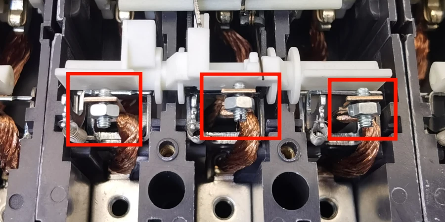
Step 5 – Lock the Setting
Once the breaker passes the test, the calibration setting needs to be fixed so it does not change during assembly, transportation, or use.
The exact method depends on the breaker design. Some designs use a locking nut, while others use sealant or adhesive to hold the calibration screw in place.
Final Thoughts
Thermal sensitivity mainly comes down to the gap between the bimetal strip and the trip bar. The basic process is simple: test, adjust, test again, and make sure the breaker meets the required range.
For multipole breakers, each pole needs to be calibrated separately and the setting should be fixed after calibration. The equipment may change with production volume, but the basic principle stays the same.