
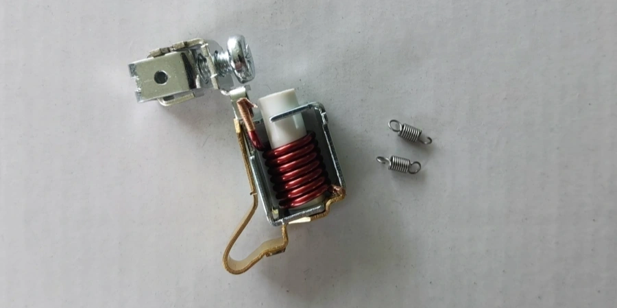
For beginners setting up their own MCB production line, one of the first things to figure out is how to control the breaker’s trip curve during assembly.
You may have the rated current sorted out, but there is another question: if the breaker hasn’t been marked B63, C32, or another curve designation yet, how do you know which trip curve you are actually building?
The answer lies in the components and settings inside the breaker. So before looking at the final marking, let’s take a closer look at what actually determines the trip curve during the assembly process.
Why the Printed Code on a Finished Breaker Won’t Help You?
If you buy a finished MCB, the answer is easy. You look at the front, read “C63” or “B32” or “D16,” and you’re done. Factories will print that labels on the breaker before it ships, and honestly, even my grandmother could learn to read it in five minutes(lol).
But that shortcut disappears the moment you’re the one building the breaker. When you receive coils, springs, and mechanisms as separate parts and start assembling them yourself, there’s no printed label yet, because the label is the last thing that goes on, not the first. What you have on your bench is a pile of components, and the trip curve is decided by how those components are put together, not by a sticker.
This is where a lot of new production teams get stuck. They assume the trip behavior is somehow baked into the breaker housing or the base plate, so they don’t pay close attention to which coil and which spring go into which unit.
Once you understand what physically sets the curve, this stops being a mystery and becomes something your line can control and check at every step.
What Actually Sets the Trip Curve?
The letters B, C, and D are simply names people agreed on. In this type of MCB mechanism, the magnetic trip point is mainly controlled by the coil and spring combination, together with the magnetic circuit and mechanical tolerances.
Change either one, and you change the current level at which the breaker trips instantaneously. You can see from the image below, even for the same MCB model, different ratings use different coil turn counts and spring forces.
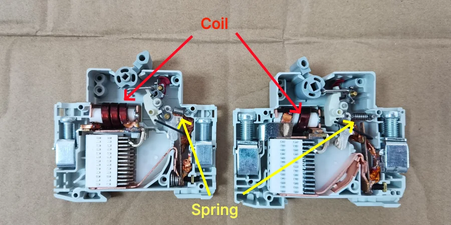
This is also how we build custom trip curves for customers. We don’t design a new mechanism from scratch each time. We adjust the coil winding and spring tension until the combination trips at the current level the customer needs.
If you’re assembling breakers yourself, this same logic applies to you: the coil and spring pairing you install is the real specification, and the printed code is just a label you add afterward to describe that pairing.
Below is a sample from a common series (1A–6A range, using the 6A coil, designation S2) from our production line, showing how the coil and spring change across ratings and curves.
| Rating | Coil | Spring – B | Spring – C | Spring – D |
|---|---|---|---|---|
| 6A | 1.0 × 19 turns | 0.3N | 0.8N | 2.5N |
| 10A | 1.32 × 11 turns | 0.1N | 0.8N | 2.5N |
| 16A | 1.55 × 7 turns | 0.3N | 1.5N | 3.5N |
| 25A | 2.12 × 5 turns | 0.3N | 1.8N | 5.5N |
| 32A | 2.37 × 4 turns | 0.3N | 2.0N | 5.0N |
| 40A | 2.37 × 4 turns | 0.8N | 2.5N | 5.0–5.5N |
| 63A | 2.21 × 3.72 × 2 turns | 0.4N | 1.5N | 4.5N |
Reading This Table on Your Own Line
Notice that the coil wire size and turn count are tied to the current rating, while the spring force changes across the B, C, and D columns for that same rating.
So a 16A breaker uses the same coil no matter which curve you’re building, but you swap in a different spring depending on whether you want B, C, or D behavior.
This is exactly the kind of detail that matters when you’re doing your own assembly, because picking the wrong spring off the shelf is an easy mistake to make and it won’t show up until you test the finished unit.
Different MCB series might have their own values, so this table is a sample, not a universal chart. If you need the full set for a series you’re building, drop us a message, and we’ll help you figure it out.
Checking the Magnetic Trip After Assembly
Once the breaker has been assembled according to the correct coil and spring combination, the job isn’t finished yet. You still need to test the finished breaker to make sure the actual magnetic trip point matches the curve you’re trying to produce.
The component combination gives you the starting point, but the test is what confirms the final result.
| Curve | No-Trip Threshold | Trip Threshold |
|---|---|---|
| B | 3 × In | 5 × In |
| C | 5 × In | 10 × In |
| D | 10 × In | 20 × In |
For example, if you’re assembling a C-curve breaker, it should not trip at 5 times the rated current within the specified test time, but it should trip when the current reaches 10 times the rated current.
This is why you can’t simply install the coil and spring according to a table and assume the breaker is correct. After assembly, the finished unit still needs to go through the magnetic trip test.
Why the Test Equipment Matters
The magnetic trip happens very quickly, so the test equipment needs to deliver the required current quickly and measure the trip response accurately.
The same test current also means different things for different ratings. A 10A test current is already 5 × In for a 2A breaker, but only about 0.63 × In for a 16A breaker.
So before testing, set the correct test current according to the breaker’s rated current and target curve. Don’t simply use the same current value for every rating.
Manual Test Benches vs Automatic Lines
Once you know what needs to be tested, the next question is how to test it efficiently on your production line.
Which equipment makes sense depends mostly on how many breakers you’re producing and how tight your margins are on testing time.
| Aspect | Manual Test Bench | Automatic Line |
|---|---|---|
| Best fit | Low volume, prototyping | High volume production |
| Operation | Technician applies current, reads trip time | Breakers move through stations without an operator |
| Data logging | Recorded by hand | Automatic pass/fail and data logging |
| Capital cost | Lower | Higher |
| Throughput | Slower | Faster |
A manual bench is a reasonable starting point if you’re still working out your curve mix or testing a new product line in small batches. You apply the current, watch the timer, and record the result yourself. It costs less to set up, but it’s slow, and it depends on a technician making consistent judgment calls.
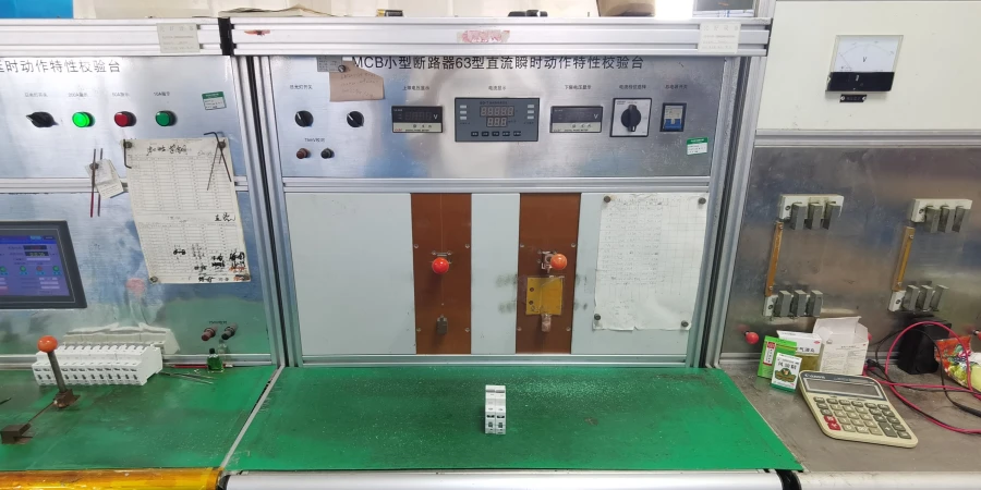
Once your volume grows, an automatic line becomes worth the investment. These integrate thermal calibration, magnetic trip testing, and often dielectric and mechanical tests into one sequence, with breakers moving through stations and getting sorted automatically.
Several equipment suppliers, including some based here in Yueqing, offer PC-based systems with independent current sources per station, which lets you run different curve types through the same line without reconfiguring everything by hand each time.
Final Thoughts
If you’re building MCBs yourself, the trip curve is one of those details that looks simple from the outside but requires careful control during assembly.
You don’t need to overcomplicate it at the beginning. Start with a clear component setup, a reliable test method, and equipment that matches your production volume. Once the process is stable, increasing capacity becomes much easier.
That’s really the goal: make the trip curve repeatable, not just get one breaker to pass the test.